A temporary voltage exceeding a circuit's intended maximum voltage.
Electrical and electronic circuits have voltage protect as part of providing the power necessary for their operation. Such voltage is typically constant and low, i.e., tens of volts, hundreds in some cases. An overvoltage is a condition occurring when a voltage impressed upon a circuit exceeds the circuit's specified operational voltage. A transient overvoltage means the duration of the overvoltage is brief compared to the time a circuit's operational voltage is applied. A garden variety transient overvoltage might last tens of microseconds (millionth of a second) and reach hundreds of volts, sometimes thousands of volts in amplitude.
They can disrupt, damage or destroy electronic circuits.
Circuits use combinations of conductors and insulators to direct and control signal currents. Examples of conductors and insulators include an insulated wire, a printed wiring board, or the metalized and doped regions of a semiconductor transistor.
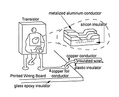 Insulating materials are capable of resisting voltage depending upon their type and thickness. Once it's resisting capability is exceeded, the insulator can break down allowing unwanted current to flow. A brief, low amplitude breakdown current can disrupt circuit operation while not doing permanent damage. A longer, higher amplitude breakdown current can damage the circuit while allowing it to continue operation with diminished capacity. Lengthy high level breakdown currents can destroy circuits.
The greater use of fragile electronic circuits in place of rugged electrical ones has resulted in transient overvoltages becoming more of a concern in recent years. For example, compare the use of a rugged electromechanical relay as a switch to a low voltage power transistor capable of handling the same load current. The relay may be bulkier, slower, less reliable, less durable and more costly but has an overvoltage immunity one thousand times greater than the transistor! To take advantage of the numerous benefits of the transistor in a hostile environment, transient overvoltage protection is recommended.
Rapidly changing or high current sources such as switches or lightning strikes.
Transients from switching can be due to: 1) appliances or equipment turning on or off 2) arcing across relay/contactor terminals or mercury switches, 3) power system grid switching or power-factor correction capacitor switching, 4) power system faults, e.g., shorts or arcing resulting in fuse clearing or circuit breaker actuation. Lightning is a cloud to cloud or cloud to earth discharge of atmospheric electricity. Electrical charges accumulate creating a voltage difference across the discharge points high enough to breakdown or ionize the air in between. A conductive path is created allowing an average of three strokes of current with median values, depending upon the exposure, from less than 10 to more than 30 kA. These brief but very intense currents create overvoltages by a direct strike or more commonly by induction from nearby strikes. Geographic variations in lightning strike frequency range from virtually none to many every other day. Lightning damage is also heavily influenced by the electrical resistance of the ground where it strikes. This resistance can vary 1000 to 1 between diverse locations.
Transients are commonly coupled in from a nearby source or in rare instances get in by direct contact with a source.
Transients are coupled resistively, capacitively or inductively. Resistive coupling can occur when high level transient currents pass through a ground path whose resistance is not zero. The high level current can develop significant voltage (even in a low resistance ground) which affects other equipment on the same grounding system. Capacitive coupling occurs because wires near one another exhibit capacitance between them. Even small capacitances can couple transients when rapidly changing voltages exist on one of the wires. Inductive coupling occurs when rapidly changing currents generate rapidly changing magnetic fields, which induce currents in nearby wires. This is done intentionally in a controlled manner with electrical transformers in many applications. Since transients simultaneously involve rapidly changing voltages and high amplitude currents, different forms of coupling can occur at the same time. For example, a rapidly rising, lightning current can couple two ways. Resistive coupling results when the high amplitude current causes the system ground to rise above earth ground. This affects all equipment connected to the elevated system ground. Inductive coupling results when the same surge currents varying magnetic field deposits energy into nearby wiring.
Inserting protective components or circuits between the input/output wires and the sensitive circuits, prevent the overvoltages from getting through.
A transient’s current, voltage and energy can easily overpower circuits not designed to handle them resulting in equipment disruption, damage or destruction. Transient overvoltage protectors, designed to deal with such threats, should be placed at equipment interfaces between the equipment and the field wiring. Here, they can withstand and reduce the transient to a level tolerable by the equipment.
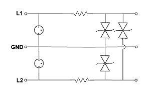
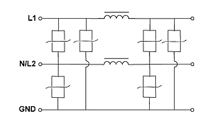
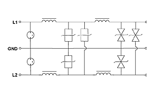
Rugged components (such as MOV’s, GDT’s, TVSD’s, Resistors, Inductors and Capacitors) are used to divert, dissipate and block transient currents/voltages and power, preventing them from reaching and damaging sensitive circuits.
Many protectors work by conducting when the overvoltage reaches a threshold above normal operating levels. This conduction by an MOV or a TVS diode is intended to retard further increases in voltage by loading the transient. An MOV can handle high transient currents but still has significant resistance while conducting, thus allowing the voltage due to the transient to continue to rise. The TVS diode has much lower conducting resistance thus exhibiting much better clamping of the transient voltage. However, the TVS diode can only handle transient currents a fraction of those an MOV can safely handle. A GDT handles very high transient currents once it ionizes and its voltage drops to twenty volts; however, the transient voltage must reach hundreds of volts to cause ionization. Each component type has its strong and weak points. Multi-component circuits improve protection by combining complementary components. For example, a two-stage data line circuit uses a very rugged GDT on the input and a not so rugged TVS diode separated by a ten-ohm resistor on the output. When a fast rising overvoltage is applied to this circuit, the TVS diode immediately clamps the output voltage while the resistor provides isolation allowing the input voltage to continue to rise for the few microseconds it takes for the GDT to ionize. The ionized GDT drops the input voltage, which in turn drops the voltage across the resistor and hence the transient current in the TVS diode. Together these components provide: 1) immediate, excellent clamping and 2) the ability to handle very high transient currents. Separately, the GDT or TVS diode provides one but not the other.
Most properly selected protectors have minimal affect on protected equipment during normal operation. However, protectors using GDTs and similar devices that clamp at low voltages after activation can disrupt equipment operation during the transient and until they recover to the non-conducting state.
The ideal overvoltage protector would be lossless thus totally transparent to normal operation. Practical protectors have losses due to some small series resistance in the signal or power path and some large but not infinite shunt resistance connected to this path. Small series resistance causes small drops in voltage and limits series current to that allowed by the power rating of the series resistor or inductor. Shunt resistance allows small leakage currents causing slight signal losses. Series inductance or shunt capacitance results in losses that increase with signal frequency. Well-designed protectors have minimal losses in intended applications.
A protector is selected to provide the protection needed without adversely affecting normal operation. Typically, electrical compatibility is established before physical features such as interface and mounting methods are selected.
The protection needed relates to the protected equipment’s transient susceptibility. Unfortunately, the transient susceptibility of most equipment is not characterized, let alone specified. However, as a generalization, the voltage levels at which disruption, damage or destruction occurs, are well above levels encountered in normal operation. This is because the insulation materials used in most applications are rarely just sufficient for the intended purpose. Often, the limited insulation material choices have breakdown voltages well beyond operational voltages resulting in substantial design margins. Consequently, a protector designed to activate just beyond normal operational levels will provide significant protection relative to levels required to disrupt, damage or destroy. Hence, specific or detailed information about equipment’s transient susceptibility is rarely needed to provide excellent transient overvoltage protection.
A line is a single circuit path. A loop is a pair of lines forming a complete circuit such as a four to twenty milliamp analog loop.
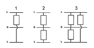
2)Line to ground Mode (L-G), Common or Longitudinal
3)Line to Line AND Line to Ground Modes (L-L and L-G)

S=Series Component
L=Load
The basic components are Metal Oxide Varistors(MOV), Gas Discharge Tubes(GDT), Transient Voltage Suppression Diodes(TVSD), Resistors, Inductors, and Capacitors.
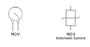
Metal Oxide Varistor (MOV)
An MOV is a voltage dependent resistor typically made of a large cylindrical block of zinc oxide grains. They act like semiconductors, an insulator below the conduction voltage and a low value resistor above it. MOVs are selected for a conduction voltage ten to fifteen percent above system maximum operating voltage so that they have significant current only when transients drive voltage levels well beyond normal system voltages. While conducting, the MOV diverts and dissipates the transient.
-submicrosecond response time
-good voltage conduction clamping
-handles high impulse currents
-rugged
Con
-high conduction voltage yields high transient power dissipation limiting impulse current handling capability
-large relative size
-high relative capacitance
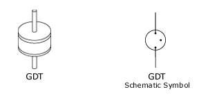
A GDT is made from two metallic electrodes arranged with a sealed ceramic tube creating a gap which is filled with an inert mixture of gases. A voltage of sufficient amplitude applied across the electrodes causes the gap gas to ionize allowing current to flow. Once ionized, the voltage between electrodes drops to 10-30V until the transient overvoltage passes; then the GDT can recover to the non-conducting state. While conducting, the GDT diverts and dissipates the transient.
-handles very high impulse currents
-low capacitance, 1-5pF
-rugged and compact
-low conduction voltage
Con
-2 o 3 us response time
-extinguishing not guaranteed
-breakdown voltage depends on transient rise time allowing high overshoot voltage
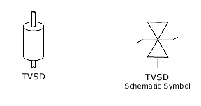
A TVSD is a semiconductor diode operating in the reverse avalanche junction mode. TVSDs are designed with extra large junction areas and low intrinsic resistivity to allow them to conduct large impulse currents without overheating. They are available as unipolar or bipolar devices, from a few hundred to thousands of Watts at voltages from less than ten to over two hundred Volts. While conducting the TVS diode diverts and dissipates the transient.
-excellent voltage clamping
-sub nanosecond response time
-compact
Con
-limited impulse or current capability
-high conduction voltage yields high transient dissipation limiting impulse current capability
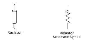
Resistors can be made from a compressed block of resistive material with leads. Transient overvoltage protectors need resistors with substantial overload protection. A half watt power resistor with a surge capability of five times the power rating is typical. Resistance values vary with application but are typically kept low in the five to ten to fifteen ohms range to avoid excessive losses while carrying normal operating currents. A resistor’s role is to isolate protector stages allowing them to operate with some independence.
-limit surge current to output stage
-substantial overload capability
-compact and rugged
Con
-line currents are limited due to resistor power ratings
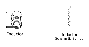
An inductor can be made with a group of tightly packed, continuous loops of wire, often around a magnetic core. Inductors resist any change in current through them. Inductors allow stage isolation for higher frequency transients while keeping losses due to normal, low frequency, operating current low.
-low operating losses allow much higher lead currents
Con
-more costly than resistors
-bulkier than resistors
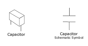
Basically a capacitor consists of two conducting plates separated by an insulator. Capacitors L-L or L-G have little affect on low frequency, operating signals but are attenuating loads for higher frequency transients.
-low operating loss
Con
-bulky
Sample Data Line Protector Circuit